PXS Telecom Solutions for CDR Collection

CDR Collection Made Easy

Ulrich Richers

Advanced Relay Corporation

The Existing Topology

The Existing Topology
Telecom companies commonly collect CDR files from a network of various types of phone switches distributed over their territory. The switches use legacy protocols, such as X.25 and often proprietary file transfer protocols, such as AFT, FTAM, AMATPS and XFER. The switches connect through a Network Interface Unit (NIU) (such as a modem, DSU/CSU device or ISDN TA) point-to-point or through private networks (X.25, PSTN, ISDN) to a centralized site. One or more gateways convert the legacy/proprietary protocol into FTP and forward the CDR files to a central collector using the Telecom's intranet. Because of this design, all protocol layers traverse the distance between switch and gateway, causing considerable delays. The NIUs are often vintage devices from different vendors with no or sketchy documentation, creating maintenance nightmares. The gateways themselves are often obsolete, such as DEC α-servers.
Legend
Legend

The Existing Protocols

The Existing Protocols
All protocol layers at the phone switch communicate via their peers to a remote gateway. All LAPB protocol messages, such as S-Frames, have to traverse back and forth between the endpoints. The gateways often use proprietary hardware and software, and support and maintenance are difficult to get.
Legend
Legend

Proposed PXS Topology

Proposed PXS Topology
The greatest advantage of the PXS solution - the PXS terminates all legacy and proprietary protocols right at the switch. Propagation delay is local and CDR files are immediately forwarded via FTP or SFTP through the Telecom intranet to the CDR file collector. This is paramount, providing the switch with an (S)FTP/Ethernet interface, much simpler than, for instance, a PTT/XOT/X.25 solution. It greatly simplifies the network and its maintenance. Further, since the PXS provides the clock (DCE), it can normally increase the speed of the connection. Additional useful remote services to the PXS are available: web server, system logs, SNMP, SMTP, DLM and APIUS (Automatic PXS Installation and Update Service).
Legend
Legend

Proposed PXS Protocols

Proposed PXS Protocols
By terminating the legacy and switch vendor's proprietary protocols right at the switch and therefore eliminating the X.25, PSTN or ISDN network, propagation delays are eliminated as well. The CDR files are now directly transferred to the CDR collector. The intranet does not have the speed limitations of an ISDN network, for instance, where the B-Channel is limited to 64 kbps. X.25 PSDN connections are normally limited to 64/56 kbps. Modem connections are generally 2.4 to 19.2 kbps.
Legend
Legend

Telecom Test Setup

Telecom Test Setup
Replacing an existing topology with our PXS solution requires knowledge about the current setup. Since legacy hardware and software are often insufficient documented, verification of the existing physical and protocol connections is required. X.25 is a standard recommendation, but there are various flavors and configuration profiles. Proprietary file transfer protocols often differ from the documentation. Protocol Analysis is the best way to verify the connection. Most important is the physical connection. More than 80% of all communication problems are caused by incorrect pin-layouts and cables. The best scenario is a test site where test CDR files can be sent from the switch to an existing collector. In absent of a test site, a live switch can be used. In some cases the switch manufacturer's technical support may be able to remotely connect to that switch and initiate the transmission of test files. Otherwise, live data will be used. We are normally only interested in the protocol part of the transmission and not the user data. Most important is to have a qualified technical person available from the Telecom company and, if possible, also from the switch manufacturer.
Legend
Legend

Secure Remote Connection from ARC

Secure Remote Connection from ARC
If a qualified technical support person from the Telecom and the switch manufacturer is available, 
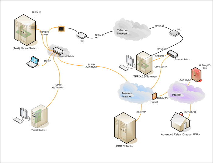
we can remotely control the tests from our facility in Eugene, Oregon. For the tests we need a PC with Windows XP Professional English version 
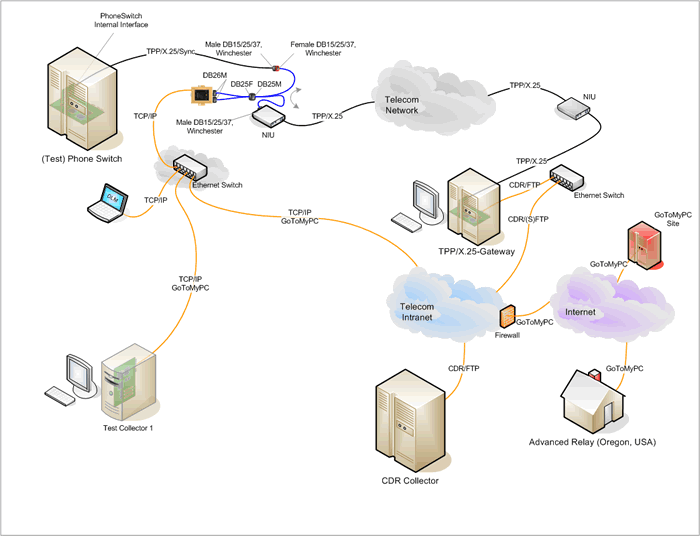
installed. We will also provide one or two PXS units and the specified cables. A breakout-box, DB25 gender-changer and DB25 RS-422 Null-Modem plug will be very useful. Also, the customer should be prepared to 
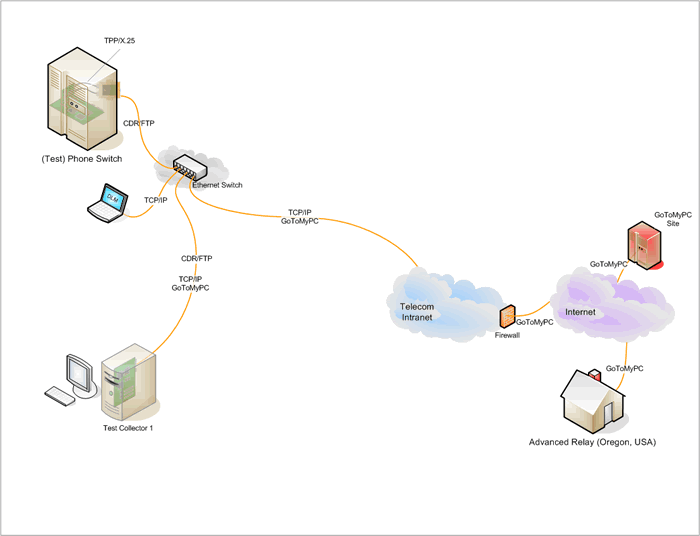
resolder cables if required. To provide a secure connection we recommend 
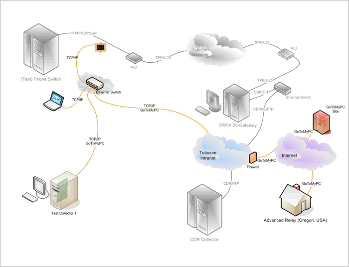
using the services of GoToMyPC, an mediator that ensures secure connection from our office to the test site. Otherwise, a VPN connection can be used. 
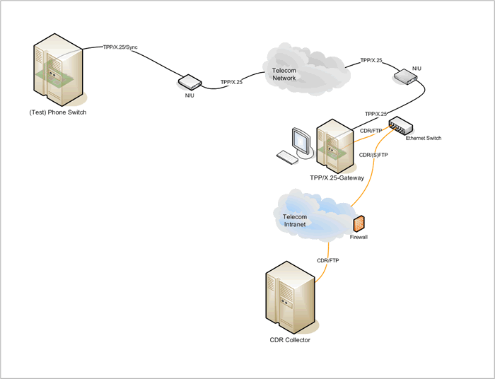
Through the secure connection, we can access the Windows XP PC and the PXS. Both should be connected to a local 100 Mbps Ethernet switch.
Legend
Legend

PXS as DLM Tap of Existing Connection

PXS as DLM Tap of Existing Connection
Once we have access to the on-site XP system and the PXS, we reprogram the PXS to operate as passive Data Line Monitor (DLM Tap). We will provide the proper cable set, consisting of 2 Y-cables, one to connect DTE-DCE and the other to connect to each PXS synchronous port. The first Y-cable can be either DB25 (M/F) and can be used for RS-232 and RS-530, X.21 DB15 (M/F) or V.35 Winchester (M/F). Other cable plugs, like RS-499 (V.36) use DB37 connectors and would have to be specially ordered. Once connected, we can then monitor one or multiple file transfer sessions from the phone switch to the collector, and record them either on the DLM (notebook), or the test collector, or at ARC's facility. We can then replay the session and analyze the protocol, and if required make changes to our protocol software.
Legend
Legend

PXS as TCP/IP Tunnel of Existing Connection

PXS as TCP/IP Tunnel of Existing Connection
This test setup is an interim step and may not be required. It allows us to tunnel the data traffic from the switch through a TCP/IP connection. This is significant because it demonstrates that the low speed network could be replaced by a TCP/IP WAN. At the same time we can activate our DLM Software Tap to continue monitoring and capturing CDR file transfer sessions for later replay. This setup would also allow us to measure the current data throughput and introducing errors to analyze the current error recovery. Once a layer is analyzed, it can then be tested by routing the switch connection to the test collector, and if working it can implemented into the PXS, moving the tunnel one layer higher. Once all layers work correctly, we redirect the CDR file collection to the test collector.
Legend
Legend

PXS as TPP-X.25↔FTP-TCP/IP Gateway

PXS as TPP-X.25↔FTP-TCP/IP Gateway
We now detach the Telecom network and associated equipment and the TPP-to-FTP gateway. CDR files will now be sent directly from the switch to the test collector. We will be able to test throughput improvement and determine the switch maximum supported speed. It will be essential to have access to a switch Specialists familiar with the switch hardware and software. We will also tune X.25 and file transfer protocol parameters to possibly increase throughput. We will be able to measure the throughput between the switch and test collector.
Legend
Legend

PXS with Dual TPP↔FTP Gateway

PXS with Dual TPP↔FTP Gateway
We are adding a second synchronous connection from the switch to the PXS. We verify the file transfer protocol for dual connection and measure the throughput. By adding a second synchronous connection, we hope to double the throughput. Here we need to know if and at what layer a multi-link protocol is used.
Legend
Legend

PXS TPP↔FTP Gateway - Dual Collectors

PXS TPP↔FTP Gateway - Dual Collectors
For redundancy we now add a second test collector and repeat the tests as before, but collecting identical CDR files on two distinct collectors. This accomplished, Collector 1 will forward the CDR file to Collector 2. After completion of transfer, we will verify that both files are identical. We will measure and document the maximum throughput for each scenario. Both test collectors using a heartbeat to ensure each other's functionality. If the primary test collector fails, the PXS will automatically send the CDR files to the secondary test collector.
Legend
Legend

PXS TPP↔SFTP Gateway - Dual Collectors

PXS TPP↔SFTP Gateway - Dual Collectors
We repeat the test as before, but we now add Secure FTP (SFTP) connection to the transfer of CDR files. The PXS will operate as SFTP client, the test collectors as SFTP servers.
Legend
Legend

PXS and Remote Control Communication Server

PXS and Remote Control Communication Server
At this point we test all the client/server functions required by the Telecom company. The communication between PXS Manager and PXS through the PXS built-in web server, the Remote Application Client, the Log Server, the APIUS (Automatic PXS Installation and Update Service), SNMP, NTP, SFTP, DHCP, DNS Server and the DLM Server and GUI Decoder.
Legend
Legend

PXS TPP↔SFTP Gateway - Dual Switches

PXS TPP↔SFTP Gateway - Dual Switches
We now add a PC emulating a second switch. This test requires that we develop a switch emulator. We test if the test collector can simultaneously collect CDR files from two distinct switches. We will collect data simultaneously using 1 or 2 physical connections on each switch. We will measure and document throughput changes. This will allow us to test multiple simultaneous sessions to the test collectors.
Legend
Legend

PXS X Connect TPP↔SFTP Gateway - Dual Switches

PXS X Connect TPP↔SFTP Gateway - Dual Switches
There are cases where switches can take advantage if their close proximity each other. Rather than using dual connections from one PXS to the switch or switch emulator, we now cross-connect and test the hot standby redundant mode. We will disconnect each connection and power off one PXS at a time and verify that the data collection continues. We will measure and document the maximum throughput for each scenario.
Legend
Legend

PXS TPP↔SFTP Gateway - Dual Emulators

PXS TPP↔SFTP Gateway - Dual Emulators
Not to monopolize the switch under test, we now replace that switch with a second switch emulator to address and test additional functionality: Remote Software Support, Software Updates and Maintenance, Remote Configuration, SNMP, SMTP, SFTP, and others. Both switch emulators and collectors, including the PXS devices, Ethernet switch and CAT5 cables can be replicated and constitute a possible alternative for the Telecom test site and used by other Telecom operations. The Telecom will need to modify their test site to reflect the new topology.
Legend
Legend

PXS X Connect TPP↔SFTP Gateway - Dual Emulators

PXS X Connect TPP↔SFTP Gateway - Dual Emulators
As before we also run in this configuration the switch redundant hot-standby mode.
Legend
Legend