The X.25 Packet Layer protocol is divided into 3 sublayers.
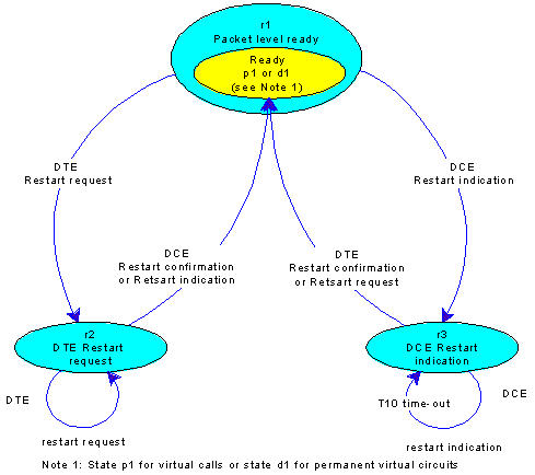
Sublayer 1 handles the communication of the X.25 major device using logical channel 0. After an exchange of restart packets (Figure 6-1), the major device enters the packet level ready state (r1) of the sublayer 1 state machine. At the same time, all minor devices (logical channels other than 0) are initialized to either ready state (p1) of the sublayer 2 state machine for Switched Virtual Circuits (SVCs) or data transfer state (p4) of the sublayer 2 state machine for Permanent Virtual Circuits (PVCs).
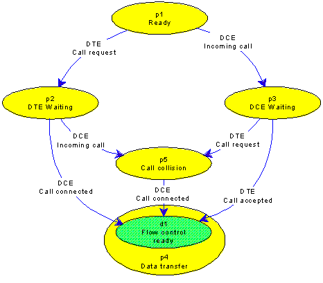
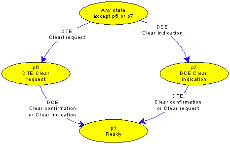
Sublayer 2 handles the call setup and clearing phases for SVCs, with each phase represented by its own state machine (Figures 6-2 and 6-3). After successfully establishing a call, the logical channel enters data transfer state (p4). At the same time, the logical channel is initialized to the flow control ready state (d1) of the sublayer 3 state machine.
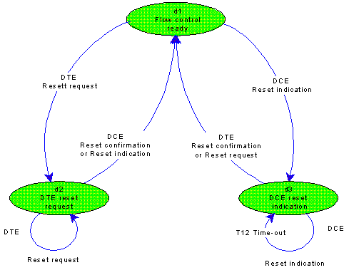
Sublayer 3 handles the exchange of data, flow-control and reset packets in data transfer state (p4) (Figure 6-4).
A restart on sublayer 1 causes a transition of all SVCs back to the ready state (p1), regardless of their sublayer 2 or sublayer 3 states. A clear on sublayer 2 causes a transition of that SVC back to the ready state (p1), regardless of its sublayer 3 state.